Showing posts with label etalon. Show all posts

Wednesday, November 25, 2009

What's and Etalon, and How do I Make One?

For those who have googled "what's an etalon?" the returned results outlining complex looking optical equations, mathmatical relationships, and technical references probably didn't do much to answer the question. Unless you are an Optical Physicist of course. (I love that stuff)

An etalon refers to an interference type filter typically used in Solar Telescopes because of the desire for an ultra narrow bandpass.

An etalon is probably one of the simplest designs for an optical filter utilizing some of the most precise optical specifications. Due to it both being simple and the need for precision, there are many compromises that can influence the quality of an etalon filter.

An etalon is comprised of 2 flat and parallel optical surface that have been optically coated with a high reflective dielectric layer with the high reflector layer peaking at the desired bandpass point for best results. These optical surfaces are seperated by a gap. This gap can be either air or a solid material. The light resonates in the gap by internal reflection off the highly reflective layers on the surfaces. Thru interference at this gap, only light meeting the correct angle of incidence to the surface and is not "interfered with" can pass, all other light is lost.

The main parameters that define an etalon are:

Bandpass: This is the width of the curve that defines the transmitance of the filter at 50% of the total transmision of the filter. An etalon's transmission has a broad base and a sharp peak. Typically the peak transmission should be between 80-90%, so the bandpass of the etalon will be measured between the 40-45% points. For Solar applications it is generally accepted that the lower this number, the better. Typical Solar Etalons have a bandpass of <1.0.

Bandpass is a function of the gap size between the high reflector plates. The larger the gap size, the narrower the bandpass.

Bandpass is also a function of the reflectivity of the etalon high reflector plates. The higher the reflectivity, the narrower the bandpass.

Peak Transmission: In order to obtain good contrast it is important to maximize the peak transmission while minimizing the "out of band" transmission. To explain this statement, a surface that had zero reflectivity would have 100% peak transmission. However, because there is no reflectivity in the cavity, there is no interference, and thus, no filter (bandpass). A surface with 100% R would reflect all light before it entered the cavity, thus having zero T. The compromise is somewhere in between..

Peak transmission is a function of the reflectivity of the surfaces. The higher the R, the lower the peak transmission. (in reality it isn't quite that simple)

Free Spectral Range: The free spectral range is defined as the gap between the peaks of transmission plotted againt wavelength. Huh?? An etalon produces a "comb" of peak transmission across a broad range of the visible spectrum. This would be like a hair comb. One tooth of the comb would represent a peak transmission. This comb would then be missing about 12-14 teeth before the next peak transmission, or tooth. In our case the FSR is more than 10 Angstroms. This becomes important to our ability to block the unwanted peak transmissions utilizing simpler filters. The narrower the FSR, the harder it is to block the transmissions you don't want. Letting another leak transmission thru will wash out the details.

FSR is a function of gap size. The narrower the gap, the wider the FSR.

Optical Flatness and Parallism: Probably the most critical aspects of the etalon performance.... To put it simply, the better the flatness and the parallism, the better the etalon.
The quality of an etalon is very much the function of precision polishing and gap maintainance.
When it comes to the specification of a Solar Telescope I often hear the bandpass stated out as a matter of fact. However, this bandpass is typically the theoretical value of the system based on the known paramaters of reflectivity, gap size, and optical flatness. What one should realize is that bandpass is not the all defining specification of a quality system.
I could quite easily manufacture a 0.3A bandpass filter and everyone would be happy.. Right??
Not if it's performance was any factor.. An etalon with a peak transmission of 40% and a FSR of 4A is quite easy to manufacture. But I assure you, you wouldn't want it in your scope.
When it comes to Etalons there are typically a few things to look at.. The bandpass, is of course, of very high concern as long as all other aspects of the optical system have been addressed. An FSR of greater than 10A is required in order to prevent out of band leaks. (the camel peaking it's nose under the tent) a phrase I liked when I heard it.
Peak T is also important as long as it comes with a zero baseline. Signal to noise ratio is critical because it is what makes the brights bright, and the darks dark. No-one want to see a significant orange glow in the space around the Sun's image, this simply washes out the edge details.
Contrast is just as important as bandpass in my opinion. However, there really isn't any specification for contrast ratio.
End of Part 1
Next: How do we make them?


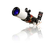


Etalons: External and Internal

Which is Better??

The defining difference between an External etalon vs an Internal etalon has typically been Price vs Performance... Well that gap is getting very narrow.

External etalons are used on the front of an existing scope, and the user typically asks that the etalon be full aperture. Internal etalons are situated internally to the scope, allowing for a full aperture objective to pass the light thru a smaller etalon due it being placed further down the optical path.

The basic rule of thumb for an etalon is the price is a function of the area. That adds up fast.

Another rule of thumb that I have heard is that the acceptance angle of an airspaced etalon is 0.5 degrees. What one should keep in mind is that, in any case, an etalon specified by surface reflection at the interface of the internal plates, thickness of gap, and gap medium only, will NOT perform to that optimal specification should there be anything other than collimated light passing thru it.

F30 does not apply specifically to airspaced etalons due to the higher index material utilized at the gap of the solid design. In most cases for solar this is solid material is Mica, and in some cases it is fused silica. All solid etalons that I have made for space flight have been fused silica.

The Sun is not a point source. In fact, the Sun is a very large extended source. It may look small at 93M miles away, but it is 865,000 miles in diameter. To put that in perspective, if the Sun were an objective and the front of your filter was the focal plane (I don't think we need to look at filter size in this example ;) the system would have an F107 ratio. That's still not entirely collimated..

Seeing the Sun at Sunset or Sunrise in relation to a distant mountain also puts it's size into perspective.

Even so, the best position for an etalon filter is on the front of the scope. However, this etalon is still compromised from ideal by the Sun's angle. These errors are small.
The use of tilt at the front etalon is simply a method of shifting the bandpass (the frequency of light passing thru the etalon). Due to the acceptance angle of the etalon, this tilt must remain very small. The more the tilt, the wider the bandpass becomes, and the non-collimated Sun angles begin to play a factor.

Tilting was introduced many years ago as a way of allowing etalons to be mass produced at slightly above the Ha line. They could then be tilted on line to accomodate the users changes in altitude and changes in barometric pressure at any given location. Without tilt, Solar Telescopes would be many times more expensive than they are today.

The move to internal etalons was done in order to bring the manufacturing costs of the Solar Telescopes down to less than 1k. By utilizing an etalon that was half the diameter of one required for the front, the cost of the etalon was cut by more than half. Even with the added cost of re-collimating and re-focus lenses, the system realized significant gains in affordability.

One of the huge benefits to internal etalons has been the fact that we only deal in one wavelength of light. This allows for the optimization of the internal lens system to remain fairly simple and straight forward. Ha! Right.. Simply aligning and collimating 4 optics now..

The evolution of internal etalons has taken several steps.
The original systems had internal fixed etalons that sat behind a re-collimating lens set (these lenses work to bring the light rays back to parallel). The light from the etalon was then re-focused back to the image plane.

These systems cannot compensate for changes in altitude and air pressure. Taking this system from sea level to 8,000ft would not work.

The next step is the introduction of some tilt. This works similar to the tilt on the front of a system. However, due to both off axis light rays that could not be re-collimated with a simple lens, and the angles created by the Sun's size, the etalon can only be tilted thru a fraction of a front mounted system. These etalons have been designed to be only very slightly higher than the Ha line so minimal tilt is required. Front mounted etalon designs can be used for this process, but recent innovations to coatings on the etalon cannot be used due to the new design's slightly narrower acceptance angle.

These systems maintain a very good flat field of narrow bandpass due to the optimization of the collimating set at Ha over about 80% of the entire field. Etalons with a theoretical bandpass of 0.65A are used, but are specified internally at 0.75A over the entire field due to the compromise of the ray angles. The center portion of these systems is typically better than 0.7A.

The current technology is the Doppler True tuning design.
The technology came about for the simple reason that tilted internal etalons are not optimized. The ideal design calls for an internal etalon (to reduce cost) in a perfectly collimated system, without the need for tilt, while also compensating for altitude and pressure changes (or being isolated from).
The new system may be simple, but it addresses 99% of all the relevant issues.

The incorporation of the air pressure system (see other blog entries for description of how this works ) has allowed us to improve the technology of the high reflector layers.
For a given optical system, we have been able to modify the design of the HR. We are still working on tweaks and changes, but have already seen some improvement to resolution, field flatness, and contrast. The new designs are moving in an area that provides for blacker backgrounds and sharper features. There's still room for improvement..

So which is better? External or Internal??

The jury is still out on that one. It is still a function of Price vs Performance.

The new evolution of internal design has certainly gone a long way to improving the performance of internal systems. However, the added cost of the pressure system has now made the external system seem more affordable.

In my opinion the best option is to buy as much double stack system as you can afford ;)

All kidding aside. Going with an internal PT system is probably the most ideal start. Buying a system that you know you can DS later without much problem is good. The dedicated system is fully optimized and ready to go. We are familiar with these systems and can help with technical issues. We test every system that goes out. I cannot test a Lunt Filter on Your scope. I cannot answer questions about in focus etc. for Your scope.

The removal of the tilting from the internal system is providing stunning results. The ability to Doppler Shift instantly to and away from you adds a 3D feel to the image that cannot be matched. This technology has certainly improved the dedicated system.

Now... What about all that tilt on the front??

The see-saw of performance is about to swing again. Lunt will be introducing the front mounted filter system with the Pressure Tune capability in mid next year (or maybe sooner ;). These systems will be manual control and also remote operable. For those that don't have 6 foot arms for your LS160F on that really long scope, this will certainly be a must.

Next blog: What is an Etalon and how do we make them?

Tuesday, November 17, 2009

Great Activity Today !!!

Tucson, Arizona has cooled some from last week. One week ago today it was 90 degrees, today we are in the low 70s.. oooh that's chilly...

Along with the cooled temps has come some nice transparent skies. I was testing today and I am very delighted to see several good active areas and as many as 4-5 small developing areas. In addition there are filaments on the surface.. woooHooo!

I hope you get a chance to get outside and view, it's very nice to see the significant increase in activity over the last few months..

Let me know what you see..

Monday, November 16, 2009

Limited Edition LS75F/HR Un-Obstructed

A HR LS75F Un-obstructed filter with matchable BF at <0.6Angstroms (single stack).

During the process of R&D I have been working with new coating technologies that are very low stress and very high finesse. As you know, these coatings will be made available in the new LS152T.

One of our recent projects was the manufacture of some un-obstructed larger 75mm Hydrogen-alpha etalons. My intention was to build one and keep it for myself.

Due to batch costs, it was just as costly to make one as it was to make a few :)

As luck would have it, we have been able to produce a couple of these etalons and I have decided to make maybe 5 available. These filters are not part of our normal production and when they are gone, they are gone, we will not take any orders for more. They are a limited edition signature series filter. There is the possibility of matching 2 for a single DS system.

A little about the etalons:

Internal aperture obstructions are used to maintain the parallelism of the high reflector plates typical to an etalon.
Removing the internal obstructions, or feet, requires that the etalon plates be manufactured to the highest specification for flatness possible. Generally better than 100th wave.
In order to prevent stress to the plates (bending) after the coating process, the coating has to be done in a system that can put down a hard, accurate, dielectric at very low heat. This process is often refered to as ion assisted deposition.

In order to decrease the bandwidth, we had to improve the high reflector dielectric properties. However, in general the trade off has been that plates flat enough to take advantage of the improved coating, were too costly to produce. (higher R needed better flatness).

The coatings that we are currently introducing have higher finesse and lower bandpass. While also providing higher contrast (noise to signal and all that). We are making the blacker, black, and the brighter, bright. Sort of like HD for solar viewing..

I will discuss more about the coatings in a future blog..

The specifications are as follows:

Type: Single Etalon Front Mount Filter
Size: 75mm Un-obstructed
Bandpass: <0.6
FSR: 11 Angstroms
Blocking Filter: Price includes B1200
Adapter Plate: Not Included (POR)
Price: US$3,985.00
Availability: Limited from Stock (check your local dealer or call us)

These are subject to prior sale and we will NOT take orders after they are gone.

Each filter will be signed and dated.

We have a few other fun things coming up, so you will have to check back here to hear about them first. (How about an unobstructed 150????) ;)~

Tuesday, November 10, 2009

First Week of November (Last Part)

As of November 1st we officially began to move into our new expanded facilities next door. Our landlord, Steve, has been nice enough to let us store our cases, shipping containers etc. over there for the last few months until the facilities were ready. The new facilities increased our square footage by about another 40%.

The expansion incudes a few more offices, a nice education/AV area with kitchen and restrooms, and in mid area a nice big fully climate controlled room for our upcoming coating facilities with large double doors to our current assembly area. The back of the area has been heated and cooled, but is currently used as a main storage area. During the buildout of our current area, we had the fore thought to put 800 Amps of 3 phase power in, so the new area has plenty of juice to keep us going.

I'll have to get some pictures up, but it's hard to believe that we first moved in to the current building in February of 2008. The building had a small kitchen, and a lobby. There were NO bathroom facilities. (We made friends with the neighbors very quickly ;). The first 2 Continuous Polishers were working in the kitchen area on very long extension cords. I had an electric heater on one wall and an air conditioner on the other, both fighting to keep the un-insulated room at +/-1 degree.

6 months later we were able to move out of the kitchen and populate the new building just in time for our open house..

14 months later we are still expanding and I am still working very hard to increase our capacity to meet the ever growing demand.

Saturday, November 7, 2009

First Week of November (Part 1)

The first week of November has flown by. A week ago today we were getting ready for Holloween night, it'll be Thanksgiving before you know it!!.

Testing, new products, and website were the projects of the week.

The image at left is the New LS152T/PT. This is currently the largest dedicated telescope that we manufacture. This is a working prototype and was on display at PATS. It had been my intention to take it outside on the Sunday, but the mount that I was going to borrow was sold on Saturday. I did try the mount it was displayed on, but that was a drop waiting to happen.

The internal lens sets for the system are almost finished. The prototype lenses were "off the shelf" and weren't quite optimized for the system proviving only about a 70% sweetspot in the center of field. The production lenses have been designed to the optical system. They are also slightly larger than the prototype given more aperture to the beam.

The LS152 contains an unobstructed 60mm HR (high resolution) etalon. This is a new etalon design and provides for high signal to noise ratio which greatly darkens that background allowing for stunning contrast on edge details.

I have already had one person ask about the unobstructed 60mm, and before the questions are raised and the assumptions made in other forums, I will state that we will not be introducing the LS60F until Summer of 2010. Due to the very high demand for the other products, we will not be tooling this particular size at the expense of current production. Our LS60F production is currently limited to the LS152T, and takes the place of the production schedule for the LS200T.

The estimated US$ retail for this instrument is $7,495.00 (this does NOT include the CaK module). For those that have the LS200T on order you will be receiving the LS152T at no additional cost. If you purchased the CaK option for the LS200T you will also be receiving that at no additional cost. As you know, the LS200T was introduced at 5k. It was the intention to increase this price once the system was shipping and had good reviews. As I will explain in another post, the LS200T could never meet both the performance requirements that I had set for it, while also meeting the strict safety requirements. The trade offs were leading to unacceptable compromizes on both sides. Safety will always be of the highest priority to ANY solar product.

For those that choose to accept the exchange, I promise that you will be receiving a solar system that exceeds my expectaions for what the LS200T was going to do. By defualt the delays have allowed for the incorporation of a 60mm etalon instead of a 50mm. The new HR (high resolution) coatings will be incorporated standard, and the value of the package itself will provide a good return on investment should you ever choose to sell.

For those that cannot accept the exchange, we will refund any deposit in full.

Monday, November 2, 2009

Recent Trip to Mt Lemmon Sky Center

This image was recently e-mailed to me from my Landlord. He and a group from his church spent the day and part of the evening at the Mt Lemmon Sky Center.
For those that attended the Open House at Lunt Solar a year ago, you will remember the visit to 9,000 ft. It was about this time of year and although the weather was clear and sunny, the temperatures were very cold.
Shortly after the visit we donated a LS100T/PT to the facility in appreciation of their hosting the event and providing everyone with a look thru some of their large scopes. Everyone had a great time.

We chose the LS100T/PT specifically because of the high altitude. A large aperture scope in great skies without the issues of air pressure to the air spaced etalon.

I hadn't given much thought to the scope on Mt Lemmon until I received this picture. Steve and the group were wandering around the domes, when Steve recognized the name on the 100T. He'd never actually looked thru one of my larger scopes before and expressed his excitment at having the chance to look thru one of our systems "in the wild". He was very pleased with the view. Everyone in the group had a chance to view the active region of last week.

This scope was provided to allow the Center to provide visitors a chance to view the Sun. The Mt Lemmon Sky Center is open to the public, and often receives large groups of children and adults who are interested in learning more about astronomy as well as the nature of the mountain.

For more information on the Sky Center you can visit http://skycenter.arizona.edu/

The facilities were remodeled about a year ago and I have to say that they did a fantastic job. From large kitchen areas, to private bedrooms, and a first rate meeting/audio visual area.

We are hoping to visit the center at our next Solar event which is now tentatively planned for March 2010.

Friday, October 30, 2009

Pressure vs Doppler Shift (Part 3)

The diagram at left shows the system has been fully pressurized. This pressure is equivalent to about a 12,000ft altitude change.
The air inside the sealed chamber has been compressed due to the reduced volume. As a result the refractive index of the air has increased and caused the CWL of the etalon to move to the blue or high energy side of the Hydrogen wavelength.

Due to the fact that there is no tilt involved, the image field remains flat and very precise.

Traditional tilting allows the Doppler shifting across the field in a plane perpendicular to the axis of light. The user can see a change to the image that allows for the viewing of proms and then filaments. The optimum position is when the proms and surface are both fairly detailed. Overtilting will tighten the bandpass but will also produce a banding effect. The resolution under the band is higher, but at the expense of the entire field of view.

People often feel that the entire field should be as good as the area created under the band. If this were possible, the systems would be spec'd at a much lower bandpass. If a band occurs, the system has probably been over attenuated.

True Doppler Tuning allows for a shift into and away from the user. Adding a 3D component to the viewing experience.
While it has minimal effect on proms due to their being at the edge of the disk, it does have an effect on filaments and active regions.
While looking at a filament at the center of the Sun the user has the ability to Doppler shift from the base of the filament to the tip, following the filament thru it's structure toward you and away from you. Allowing for enhanced visual and imaging capability for the observer as well as a research tool for the avid hobbyist.
The tuning system provides an order of magnitude more precision to the tuning of the desired features.

We are working on designs to the LS100F and the LS100T/Na utilizing the same technology.
The LS100F will be remotely operated for those that have this filter mounted on a long FL scope and do not have 4ft long arms.
We are currently manufacturing the LS60T and the LS100T via this technology.
The LS60T is fully upgradeable to the new Pressure Tune System at any time. However, it does require a return to the factory.

End of Part 3

Pressure vs Doppler Shift (Part 2)

The diagram shown at left indicates that the air pressure inside the sealed chamber has been increased. At this point the CWL of the bandpass is at 656.28nm. At this position we are looking at the Hydrogen-alpha line and the energy associated with that wavelength.

The sealing of the cavity is done via the collimating and refocus lens so that the etalon itself is isolated from differential pressure.
The piston applies from zero to a pressure that is equivalent to taking an etalon from -500ft to +12,000ft above sea level.
This has the added benefit of making the etalon system altitude insensitive.

In addition the etalon can be used from -50 to +200 degrees Celsius due to the fact that the tuning can compensate for the very small changes that heat would have on the "feet" of the etalon.

I have gone into great detail in prior posts regarding the compromises of tilting internal to a telescope. Only very small adjustments to the tilt of an etalon can be done otherwise the etalon system will begin to suffer from the off axis rays of the re-collimated beam.
People have noted that in internal tilt systems the CWL is very sensitive to even small adjustments of the tilt wheel.
By removing the need for tilt we have placed the etalon in the most optimized position possible.
We install a very accurately tuned etalon. This etalon is tuned to the red side of the CWL. Given that it is already tuned to the red, the user has the ability to shift the tune of the CWL to the Hydrogen-alpha line and then Doppler tune to the blue or back thru to the red.

Due to the fact that there is no tilt involved, the image field remains flat and very precise.

End of Part 2

Pressure vs Doppler Shift (Part 1)

Lunt Solar Systems recently introduced the new Pressure Tune system, or Doppler True Tuning system.

The image at left shows the basic outline of this system. The internal etalon is at ambient pressure. The tuning of the etalon is slightly low, putting the Center Wavelength (CWL) at the red wing of the Hydrogen line. This provides a view of less energetic features in the Chromosphere.

How does it work and what does it do?

The system works because the etalons used in the current Lunt designs are air spaced. These air spaced etalons have been typically tuned to the Hydrogen-alpha line via several mechanisms.

The first is the spacing of the air gap between the high reflective surfaces of the ultra flat plates. By changing the spacing, you change the CWL. The distance of this spacing is generally held constant because the refractive index of the medium between the plates (air) is relatively stable at ~1.
The center wavelength can be manipulated from there by slight tilting of the etalon. This changes the angle of the light at the interface of the high reflector/air layer, having the effect of moving the center wavelength toward the blue.

Slight changes in barometric pressure and/or a change in altitude will effect the CWL due to the change in refractive index of the spacer layer.
These changes can be compensated for by additional tilting provided that the etalon is tuned to accomodate those changes.
Taking an etalon that was tuned at 100ft to 10,000ft would certainly not be within that range.

In the past I have manufactured sealed etalon systems for space flight.
These etalon systems were designed to work in a sealed vacuum. As a result they were manufactured as very highly tuned etalons. By placing them under vacuum, the tuning lowered . Tuning was done to ensure that at full vacuum the etalon was on band.
Additional fine tuning from there was done via heat due to the fact that the vacuum could not be adjusted.

Our technology utilizes air pressure and not vacuum.

End of part 1

Thursday, October 29, 2009

R&D Projects at Lunt Solar Part 1

It's probably doesn't come as any surprise that Lunt Solar Systems LLC is involved in R&D projects outside the field of Solar Filters and Telescopes.
But it is because of our highly technical and specialized skills that we are often asked to develop unique optical elements that fall within our capabilities and my interests.
Some of these R&D programs are confidencial. Some of the ongoing projects are not, and may not only be of interest, but they may encourage readers to suggest other uses for these technologies.

One of our more recent projects has been the developement of a novel solid etalon design.
The intial concept was for the design of an ulta thin, ultra stable, ultra precise, and ultra narrow bandpass micro etalon.

The project's scope of work consisted of manufacturing a solid etalon that was approximately 0.3mm thick (0.012") at the Hydrogen-alpha line.
Multiple matched etalons needed to be produced. The desired size was 4mm x 4mm.
The Hydrogn-alpha emission line was chosen due to our knowledge of manufacturing at that specific wavelength. However, Hydrogen-alpha is not the desired wavelength of the finished product.

The results have been extremely succesful.

At Lunt Solar we produced what can essencially be referred to as a wafer etalon.
The solid etalon was manufactured from a 80mm piece of low expansion UV grade material. (not zero expansion).
The "spacer" layer was polished to 0.3mm thick and send out for testing prior to further work. We needed to show verification of the spacer layer's precision prior to going to the next step.

Results:

The Wafer was first tested for surface flatness. Surface flatness was not the concern given that the etalon would be used in transmission.
It was the Transmitted Wavefront that was specified.

As you can imagine the wafer did suffer from some surface error due to being held in a fixture.

The surface flatness was measured at 1/6th of a wave, some of that coming from astigmatism due to the fixture point.
Power was the major contributing factor to this error due to the method of manufacture.

The Transmitted wavefront results were very encouraging.
The interferometer showed a peak to valley error over 75mm (the aperture of the system) of 1/61th wave at 532nm. The RMS being better than 1/250th wave (the limit of the test system).
This test was over 75mm. The system was not capable of realizing a measurement over 4mm aperture, and the engineer was not able to speculate just what that result would be could it even be measured.

These results were followed by some interesting conversations with the test facility who wanted to know how we had tested the wafer ourselves.
For those that have visited Lunt Solar in Tucson, you will know that I test ALL optics for flatness by eye only.

The wafer was sent out for coating via a low temperature, ion assisted process. The wafer was coated on both surfaces with what I now refer to as the new hybrid high reflector.
Some initial tests needed to be done to assure a "tune" at the desired wavelength.
In this case we tuned slightly low of Hydrogen-alpha in order to utilize the standard method of heat to bring the etalon accurately on band.

The end result was a pellicle wafer of about 80mm diameter. Given the highest degree of precision for the entire etalon, we could now be assured of matching etalons of 4mm x 4mm after the wafer had been diced.

The net result as far as specifications go are as follows:

Bandpass: 0.2 Angstroms
Free Spectral Range: 11 Angstroms
Finesse: 27

A few technology applications immediately come to mind given the controllable FSR and the narrow bandpass. I would certainly like to hear your thoughts on possible applications as well.

I am obviously excited about the prospect of getting this system assembled into the back end of a SCT telescope very soon. The wider acceptance angle of this design vs a conventional higher index spacer material will make the modification to existing SCTs in the market fairly simple and compact.
The fact that the etalon itself is thin and has little mass will allow for rapid temperature change and stabilization.
The use of the proven materials will allow for a mass-produceable 0.2 Angstrom bandpass system with a single etalon. I can hear the calls for a double stack system already...

Moving outside my area of expertise and free thinking for a moment...

The product is of a robust solid design and the CWL of the system can be fixed to a specific wavelength or tuneable.
The thickness of the system lends itself well to the bonding to CCDs. Maybe multiple etalons can be bonded to a single CCD to provide a chemical signature detector?
I have thought about it's use in applications such as ionized gas/chemical detection for a while.

Used in these applications the signal to background noise ratio would be of huge advantage, eliminating all background noise and providing >90% T at the desired wavelengths.

We provide 0.5A bandpass looking directly at the Sun. Ambient daylight would be of no issue.

Ancillary light sources such as laser or short wavelengths could be used to further excite the desired compounds?
Are there military applications for ionized gas/chemical detection for munitions, gunfire etc?? The addition of signature trace elements to munitions that can be optically traced?

Other applications may include laser line stabilization, optical fiber multiplexing, etc...

This is just one of our current R&D projects. It is thanks to this project and a few others which I will outline in another blog that we are rapidly improving the performance of our core products. Success and failure though our ongoing research projects are already seeing a positve impact on the contrast and resolution of even our most basic systems..

Upcoming products will focus on enhanced performance and the ability to accessorize systems for use as educational tools.

I encourage your feedback and comments and thank you for reading.